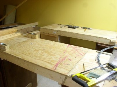
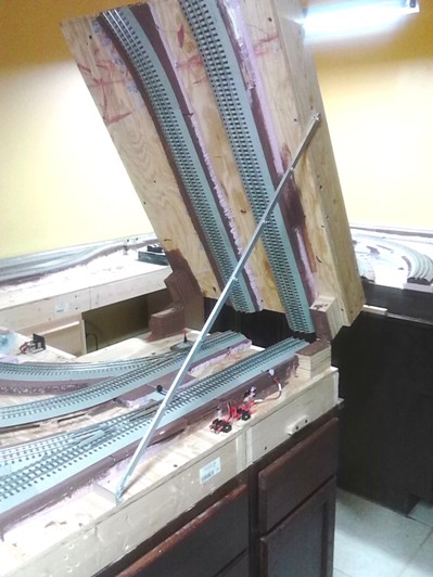
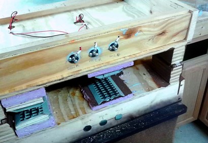
 Above: here is a view of the liftbridge from the mating edge looking back to the hinges (the two rectangular objects). Right: the bridge after track has been installed, showing how it is held open. The power will be run from the hinged side onto the bridge. I did not want the power running from the mating edge as this edge may become unstable as the wood expands or contracts. |
|
|
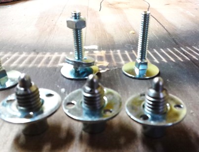
Three components: Elevator bolts w/nut (in back), brad mount T-nut, and steel plunger inserts (in front). The steel plunger inserts were bought on ebay and then the correct size of T-nut was chosen to fit them. |
 Installing the elevator bolts in the faceplate of the board from which the power will come. The center bolt is centered on the height and width of the board. |
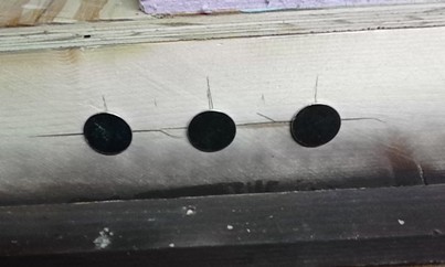 The elevator bolts are in and the wires attached to them on the inside. |
|
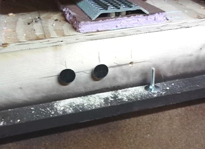
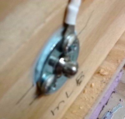
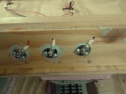
I drilled three holes in the backside of the liftbridge to line up with the elevator bolts previously installed. The T-nuts are installed with screws. The plungers are adjusted so they will contact the elevator bolts under slight pressure. The tension adjustment is made by threading them in or out of the T-nut. |
|
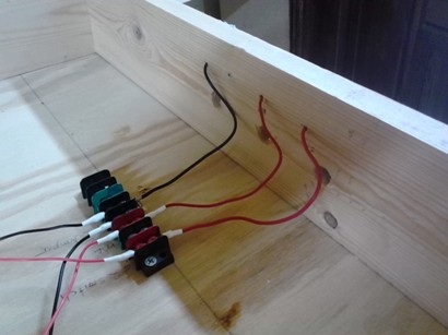
The wires have been installed on the tracks and terminate on a terminal strip. From the terminal strip, wires run through holes to the T-nuts. |
|
 Wires are secured to the T-nuts. |